
PIC10F206 blinks an LED using the Watch Dog Timer (WDT) to awaken from Sleep.
With this method, the μC can do useful work, sleep, then wake up when the delay period is completed.
The WDT has its own coarse clock with a nominal period of 18 msec. This period is multiplied using the postscaler to achieve a longer delay as shown in this spreadsheet.
The only data retained by the 10F206 during sleep are the state of the GPIO port and the cause of the Reset (to distinguish between power up and wake). So, it is possible to use the 4 GPIO bits to control a state machine through as many as 24 = 16 sleep cycles.
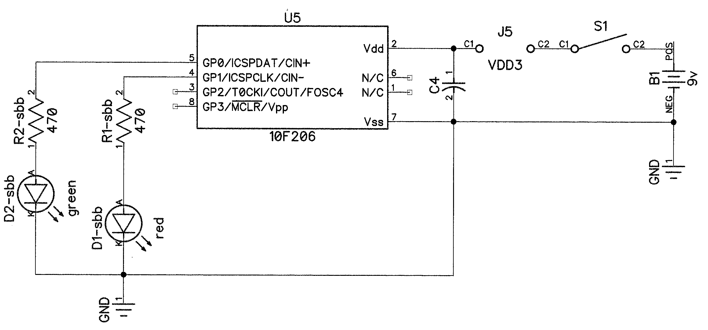
Below is the schematic. The components labeled *-sbb go on the solderless breadboard.
Show text file suitable for cut-and-paste.
/*
 * File:   lab2_1.c
 * Author: Brian
 *
 * DESCRIPTION: this version uses the Watch Dog Timer to wake the uC
 *
 * We need 0.5 second delay.
 * WDT clock period is 18 msec.
 * The available postscale multipliers and resulting total watch dog timer
 * delays are:
 *      N   Delay [msec]
 *      ------------------
 *      1   18
 *      2   36
 *      4   72
 *      8   144
 *      16  288
 *      32  576     <== closest to 500 msec
 *      64  1152
 *      128 2304
 *
 * The 10F206:
 *      a) does not retain any data memory space during SLEEP, and
 *      b) wake from SLEEP produces a Reset (starts our program from the
 *         beginning)
 *      c) maintains the setting of the GPIO latch while asleep.
 *      d) provides flags in the STATUS register which describe the cause of the
 *         power-up Reset.
 * It appears this is the best we can do.
 */

#include <xc.h>
#include <stdint.h>

// CONFIG
#pragma config WDTE = ON        // Watchdog Timer (WDT enabled)
#pragma config CP = OFF         // Code Protect (Code protection off)
#pragma config MCLRE = OFF      /* Master Clear Enable (GP3/MCLR pin fuction is
                                 * digital I/O, MCLR internally tied to VDD)
                                 */

void main(void) {
    /* Initialize I/O and Peripherals for application */
    TRISGPIO = 0b1100;  // set GP0 and GP1 as output pins
    CMPON = 0;          // disable the Comparator so we can use GP1 for IO
    OPTION = 0b11001101;
    /*
     *  OPTION bits:
     *      <2:0> PS = prescale value, 5=divide by 32
     *      3 PSA = assign prescaler, 1=WDT
     *      4 TOSE = TMR0 source edge select, don't care
     *      5 TOCS = TMR0 clock source select, 0=system clock
     *      6 notGPPU = enable weak pull-ups, 1=disable
     *      7 notGPWU = Wake up on pin change 1=disable
     */

    /*
     * check what kind of Reset got us here!
     * REF: Table 9-5
     * if PD==1 and TO==1 then power-up
     * if TO==0 then WDT expired
     */
    if (nPD && nTO) {
        // power-up has occured, so this is our "first" wake up.
        GP1 = 1;        // turn LED on
        GP0 = 1;        // to trace execution, turn OFF a 2nd LED
        SLEEP();
    }

    /*
     * execution reaches this point if-and-only-if the latest Reset is
     * NOT caused by a Power Up.
     */
    if (nTO == 0) {
        // WDT has expired, so this is a subsequent wake up.
        GP1 = ~GP1;     // read the current state of the LED and complement it.
        GP0 = 0;        // to trace execution here, turn OFF our 2nd LED
        SLEEP();
    }
}