Use PIC10F206 to blink an LED using a busy-wait.
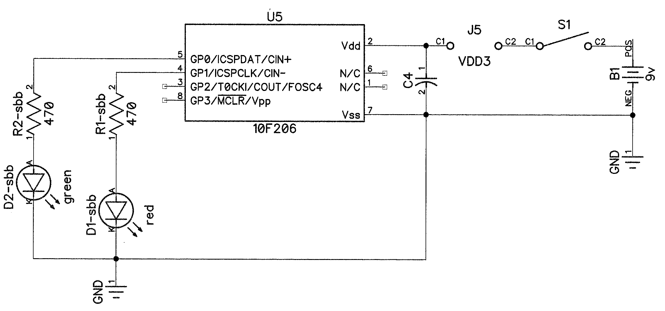
Below is the schematic. The components labeled *-sbb go on the solderless breadboard. The source code only uses D1-sbb, but Lab2_1 uses both LEDs,
Show text file suitable for cut-and-paste.
/*
 * File:   lab1.c
 * Author: Brian
 */

#include <xc.h>

#define SYS_FREQ        4000000L
#define FCY             SYS_FREQ/4 // running 1 MHz clock

// CONFIG
#pragma config WDTE = OFF       // Watchdog Timer (WDT disabled)
#pragma config CP = OFF         // Code Protect (Code protection off)
#pragma config MCLRE = OFF      /* Master Clear Enable (GP3/MCLR pin fuction is
                                 * digital I/O, MCLR internally tied to VDD)
                                 */

void main(void) {
    /* Initialize I/O and Peripherals for application */
    TRISGPIO = 0b1101;  // make GP1 an output pin
    CMPON = 0;          // disable the Comparator so we can use GP1 for IO
    while (1) {
        GP1 = 1;
        _delay(500000);
        GP1 = 0;
        _delay(500000);
    }
}